
What Do You Know About the Types and Structures of Pneumatic Punches?
There is no limit to the number of manufacturing, and fabrication systems in which pneumatic punches serve as workhorses. With compressed air, they provide quick, dependable blast to punch out a hole, cut out a shape or indent a material. The realization that their basic varieties and structure are fundamental is pertinent toward establishing their versatile nature and usage.
Core Operating Principle:
Fundamentally, pneumatic punches turn compressed air power into mechanical power. Compressed air is then forced into a cylinder and a piston is powered. Linear movement of such a piston either directly or through amplification devices sends the same to a punch tool that transmits the movement to the material doing the work.
Common Types of Pneumatic Punches:
1.Reciprocating Pneumatic Punches:
Description: The commonest kind. The pneumatic cylinder makes the punch tool move in a straight line in the process, down during the punching movement and up during the returning movement.
Sub-Types (on the basis of frame/structure):
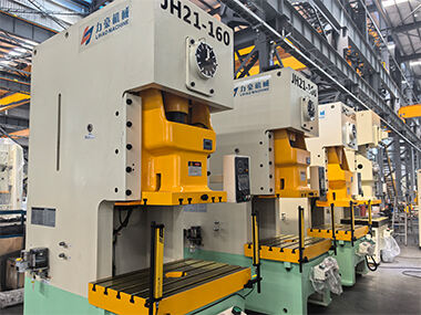
- C-Frame Punches: Have the shape of the letter C. The cylinder is positioned vertically and on the upper arm swings a punch which is driven down through the material and into a die on the lower arm/bed. Has good front and side access to the workspace. Usually typical of lighter to medium-duty works and smaller workpieces.
- O-Frame (Straight-Side) Punches: Has an entirely encapsulated/box-like construction all around the working space. The cylinder is put vertically on the top side and pushes the punch down. The rigidity, stability and accuracy of alignment of this design offers greater rigidity needed in heavier tonnage, thicker materials or precision punching where extreme accuracy is essential. It reduces deformation of the frame under loads.
2.Rotary Pneumatic Punches:
Description: They do not have a linear punch strokes; they have a rotating mechanism. A piston pushes against a crank or cam mechanism propelled by compressed air and induces linear motion of a piston into rotary motion of a turret or wheel with plural punch and die sets.
Function: Various sets of punches and dies are positioned above the workpiece as the turret spins. The hole is then punched out by separate downward actuation (usually pneumatic) of the corresponding punch. Superb where there is high velocity, repetitive punching of a variety of hole shapes or sizes without the need to change manual tools.
Key Structural Components:
Pneumatic punches of all types have core constructions in common:
1.Frame: Gives the solid support and contains the rest. Absorbs the impact-shock. Rigidity and capacity is defined by materials (cast iron, steel) and design (C-frame, O-frame).
2.Air Cylinder: An airtight section in which a compressed air force is used to push on a piston. The maximum theoretical punching force (tonnage) is a factor of cylinder bore size and air pressure.
3.Piston: encapsulated in the cylinder, it is forced to move straight by virtue of the air pressure. And its rod applies force directly to the punch holder or to an amplification mechanism.
4.Punch Holder / Ram: This is the assembly into which the punch tool is inserted and retained securely by clamping. It directly links to the piston rod (in simple designs) or rides in the frame. Starts going along with the direction of the punch stroke vertically.
5.Die Holder / Bed: The fixed or movable part which firmly supports the die. Just underneath the punch holder. The punch or die holds the material between it and the die.
6.Control valves:
- Directional Valves (e.g. Spool Valves): Accurately regulate inflow and outflow of compressed air in and out of the cylinder chambers, which determines the position (extend, retract, stop) of the pistons.
- Pressure Regulator: The pressure regulator ensures that the pressure of air being injected into the system is controlled, which renders a direct impact on the punching force which is produced.
- Flow Control Valves: Regulate rate of air used to feed or exhaust the cylinder and thus regulate the rate of the punch movement into the cylinder and back again.
7.Guiding System: Important to accuracy and durability. The punch holder/ram moves along the linear bearings or bushings to center it in the die perfectly and during the stroke the side load is minimal. The O-frame designs normally provide better directing.
8.Optional (but common) Air Reservoir: A tank of compressed air around the punch. Gives a ready supply of air to guarantee a constant stroke of punch power and most significantly in rapid and quick cycling that may lose its pressure main supply line.
9.Stroke Adjustment Mechanism (Common): Gives the operators the ability to make the distance the punch moves down. This reduces cycle time (wastes are minimized) and preserves the tooling. May be mechanical stops or sets.
Operational Characteristics Influenced by Structure:
Force (Tonnage): this is a result obtained through the cylinder bore size and air pressure. O-frames can work more tonnage-more Rigidity.
Speed (Strokes Per Minute - SPM): Depends on cylinder size, rate of air flow rate, valve speed and the mass in motion. The highest SPMs are attained by rotary punches.
Accuracy & Repeatability: Affected by frame stiffness, the quality of guiding systems and control valve accuracy. O-frames tend to assure the greatest accuracy.
Conclusion:
The pneumatic punches justify their strength of combination of high speed and cleanliness with relatively non-complicated control when boom compared to the hydraulic system. Learning the difference between reciprocating (C-frame, O-frame) versus rotary types gives an idea of their strengths of application, whether it is multi-purpose single-station operation to high-speed multi-tool operation. Their capabilities can be summed up in terms of force, speed, accuracy and durability by the underlying structure that revolves around the robust frame, powerful air cylinder, precise guiding and responsive valving. The combination of mechanics and pneumatics thus makes them very useful and inevitable tools in efficient processing of materials.